
In this example we connect a L9110 fan module to a TPyboard, in this case we I used a TPyboard 202
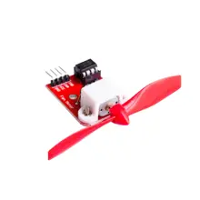
and this was the L9110 module
Description
The ASIC device control and drive motor design two-channel push-pull power amplifier discrete circuits integrated into a monolithic IC, peripheral devices and reduce the cost, improve the reliability of the whole.
This chip has two TTL / CMOS compatible with the level of the input, with good resistance; two output terminals can directly forward and reverse movement of the drive motor, it has a large current driving capability, each channel through 750 ~ 800mA of continuous current, peak current capability up to 1.5 ~ 2.0A; while it has a low output saturation voltage; built-in clamp diode reverse the impact of the current release inductive load it in the drive relays, DC motors, stepper motor or switch power tube use on safe and reliable. L9110 is widely used in toy car motor drives, stepper motor drive and switching power tube circuit.
Features:
Low quiescent current
Wide supply voltage range: 2.5V-12V
800mA continuous current output capability per channel
Lower saturation voltage
TTL / CMOS output level compatible, and can be directly connected to the CPU
Output built-in clamp diodes for inductive load
Integrated control and drive into a monolithic IC
With pin high-voltage protection function
Operating temperature: 0 ℃ -80 ℃
Parts Required
The module costs about $2
| Name | Link |
| L9110 module | L9110 Fan Module for Robot Design and Development |
| TPYBoard V202 | TPYBoard V202 Pyboard Micropython Development Board |
| Connecting cables | Free shipping Dupont line 120pcs 20cm male to male + male to female and female to female jumper wire |
Schematic/Connection
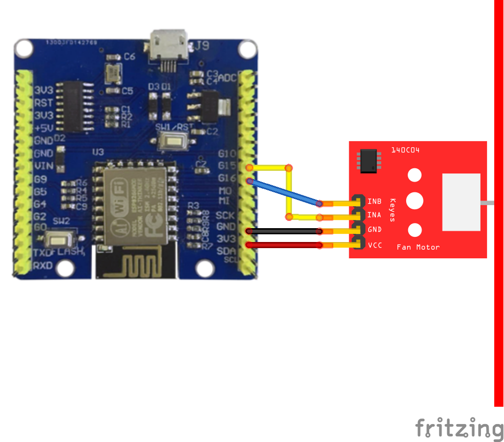
typyboard and l9110 layout
Code Example
I used uPycraft for development, no libraries required. This module simply requires a high or low on either of the 2 pins. One of these is the forward signal and the other is the backward signal
OA = A road output pin
OB = B output pin
IA = A road input pin – backward signal
IB = B input pin – Forward signal
This table shows the input value and the output
| IA | IB | OA | OB |
| H | L | H | L |
| L | H | L | H |
| L | L | L | L |
| H | H | L | L |
I used uPycraft and simply modified main.py
This is a test example in the library which pretty much highlights all of the functionality, you can also use any other Micropython supported board
[codesyntax lang=”python”]
import time
from machine import Pin

INA = Pin(15, Pin.OUT)    # create output pin on GPIO15
INB = Pin(16, Pin.OUT)    # create output pin on GPIO16

while True:
  print("direction 1")
  INA.value(1)                 # set pin to "on" (high) level
  INB.value(0)               # set pin to "off" (low) level
  time.sleep(5)
  print("direction 2")
  INA.value(0)               # set pin to "off" (high) level
  INB.value(1)              # set pin to "on" (low) level
  time.sleep(5)
[/codesyntax]
Output