
In this example we connect a TSL2561 light-to-digital converter to an Adafruit Feather M0 running Circuitpython
First lets look at some information about the sensor from the manufacturer
The TSL2561 is a light-to-digital converter that transforms light intensity to a digital signal output capable of an I2C interface.
Each device combines one broadband photodiode (visible plus infrared) and one infrared-responding photodiode on a single CMOS integrated circuit capable of providing a near photopic response over an effective 20-bit dynamic range (16-bit resolution). Two integrating ADCs convert the photodiode currents to a digital output that represents the irradiance measured on each channel.
This digital output can be input to a microprocessor where illuminance (ambient light level) in lux is derived using an empirical formula to approximate the human eye response. The TSL2561 device supports a traditional level style interrupt that remains asserted until the firmware clears it.
Features
Patented dual-diode architecture
1M:1 dynamic range
Programmable interrupt function
I²C digital interface
Product parameters
Supply Voltage [V] 2.7 – 3.6
Interface I2C – VDD
Programmable Gain, integration time, interrupt
Max. Lux 40000
Temperature Range [°C] -30 to 70
Remark
Not recommended for new designs. Please see TSL2572x device family.
This is the sensor I bought

Parts Required
| Name | Link |
| Adafruit Feather M0 Express | Adafruit (PID 3403) Feather M0 Express – Designed for CircuitPython – ATSAMD21 Cortex M0 |
| TSL2561 | TSL2561 Infrared Light Sensor Module |
| Connecting cables | Free shipping Dupont line 120pcs 20cm male to male + male to female and female to female jumper wire |
Schematic/Connection
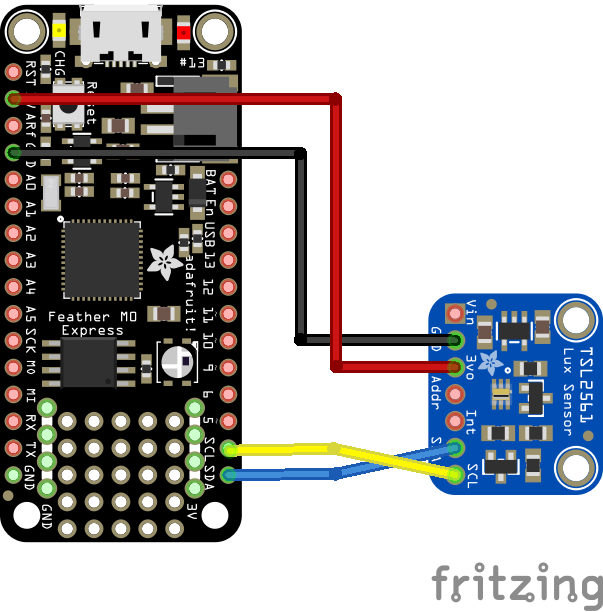
feather and TSL2561 layout
Code Example
I used Mu for development
The following is based on a library , I copied the TSL2561 library to the lib folder on my Feather M0 Express – https://circuitpython.org/libraries
[codesyntax lang=”python”]
import time
import board
import busio
import adafruit_tsl2561

# Create the I2C bus
i2c = busio.I2C(board.SCL, board.SDA)

# Create the TSL2561 instance, passing in the I2C bus
tsl = adafruit_tsl2561.TSL2561(i2c)

# Print chip info
print("Chip ID = {}".format(tsl.chip_id))
print("Enabled = {}".format(tsl.enabled))
print("Gain = {}".format(tsl.gain))
print("Integration time = {}".format(tsl.integration_time))

print("Configuring TSL2561...")

# Enable the light sensor
tsl.enabled = True
time.sleep(1)

# Set gain 0=1x, 1=16x
tsl.gain = 0

# Set integration time (0=13.7ms, 1=101ms, 2=402ms, or 3=manual)
tsl.integration_time = 1

print("Getting readings...")

# Get raw (luminosity) readings individually
broadband = tsl.broadband
infrared = tsl.infrared

# Get raw (luminosity) readings using tuple unpacking
# broadband, infrared = tsl.luminosity

# Get computed lux value (tsl.lux can return None or a float)
lux = tsl.lux

# Print results
print("Enabled = {}".format(tsl.enabled))
print("Gain = {}".format(tsl.gain))
print("Integration time = {}".format(tsl.integration_time))
print("Broadband = {}".format(broadband))
print("Infrared = {}".format(infrared))
if lux is not None:
    print("Lux = {}".format(lux))
else:
    print("Lux value is None. Possible sensor underrange or overrange.")

# Disble the light sensor (to save power)
tsl.enabled = False
[/codesyntax]
Output
Here is what I saw in Mu REPL window
Chip ID = (5, 0)
Enabled = True
Gain = 0
Integration time = 2
Configuring TSL2561…
Getting readings…
Enabled = True
Gain = 0
Integration time = 1
Broadband = 642
Infrared = 536
Lux = 21.3968
Links